This technical blog is designed to establish Aera Engineering Pvt Ltd as a thought leader in the engineering community. By providing a clear, academic-style guide on a complex calculation, you build trust with process engineers who make the final procurement decisions. In the design of a packed bed tower, one variable stands above all others in determining the efficiency of gas-liquid contact: the Packing Factor. Whether you are designing a new VOC stripper or debottlenecking a refinery column, understanding the packing factor is essential for calculating pressure drop and liquid holdup. At Aera Engineering Pvt Ltd, we provide high-precision Aera P-Rings and I-Saddles with certified packing factors, but understanding the math behind these numbers is vital for every process engineer. What is the Packing Factor ? The packing factor is an empirical constant specific to each type and size of random packing. It represents the ratio of the total surface area of the packing to the cube of the void fraction: F_p = frac{a}{epsilon^3} Where: Specific surface area ($m^2/m^3$) $epsilon$: Void fraction (dimensionless percentage of empty space in the bed) The packing factor is a direct indicator of the resistance to gas flow. A lower $F_p$ generally indicates lower pressure drop and higher capacity. The Step-by-Step Calculation Process While most engineers use the Generalized Pressure Drop Correlation (GPDC) charts, you can calculate or verify the packing factor using the following steps: 1. Determine the Specific Surface Area ($a$) This is the total geometric surface area of the individual packing pieces per unit volume of the tower. For plastic media, this is calculated by multiplying the surface area of a single piece by the number of pieces per cubic meter. 2. Calculate the Void Fraction ($epsilon$) The void fraction is the ratio of the volume of the interstices (empty spaces) to the total volume of the packed bed. $$epsilon = 1 - frac{V_{solid}}{V_{total}}$$ Plastic media like Aera Polypropylene P-Rings typically offer exceptionally high void fractions (often $>90%$), which is why they are preferred for low-pressure applications. 3. Adjust for Wall Effects and Bed Compaction In actual tower operations, the 'Dry Packing Factor' must be adjusted for 'Wet' conditions. As liquid flows down the tower, it coats the packing, effectively reducing the void fraction and increasing the functional $F_p$. Why the Packing Factor Varies Between Media Not all 25mm (1-inch) packings are created equal. The geometry significantly impacts the $F_p$: Raschig Rings: Have a relatively high $F_p$ because their 'closed' walls create more resistance. Pall Rings: The 'windows' in the walls allow gas to flow through the center, significantly lowering the $F_p$. Saddle Rings: Their aerodynamic shape provides the lowest $F_p$ among traditional random media, allowing for maximum throughput. Engineering Impact: Designing for the 'Flood Point' The packing factor is the key input for determining the Flood Point—the velocity at which the gas flow prevents the liquid from descending. High $F_p$: Leads to early flooding and high energy consumption by blower fans. Low $F_p$: Allows for higher gas and liquid loads, making the tower more resilient to process surges. Conclusion: Precision Manufacturing for Predictable Performance At Aera Engineering Pvt Ltd, we utilize precision injection molding to ensure that every batch of packing we export from Vadodara maintains a consistent geometry. This consistency is what allows engineers to rely on our published $F_p$ values for their critical simulations. Need a custom calculation for your tower? Aera Engineering provides technical support for engineers designing complex mass transfer systems. Contact our technical desk for certified $F_p$ data and material compatibility charts. [Download our Technical Design Manual] | Aera Engineering Pvt Ltd | Vadodara, India

This is your website preview.
Currently it only shows your basic business info. Start adding relevant business details such as description, images and products or services to gain your customers attention by using Boost 360 android app / iOS App / web portal.
How to Calculate the Packing Factor for Plastic Random Media
2026-04-25T04:31:35
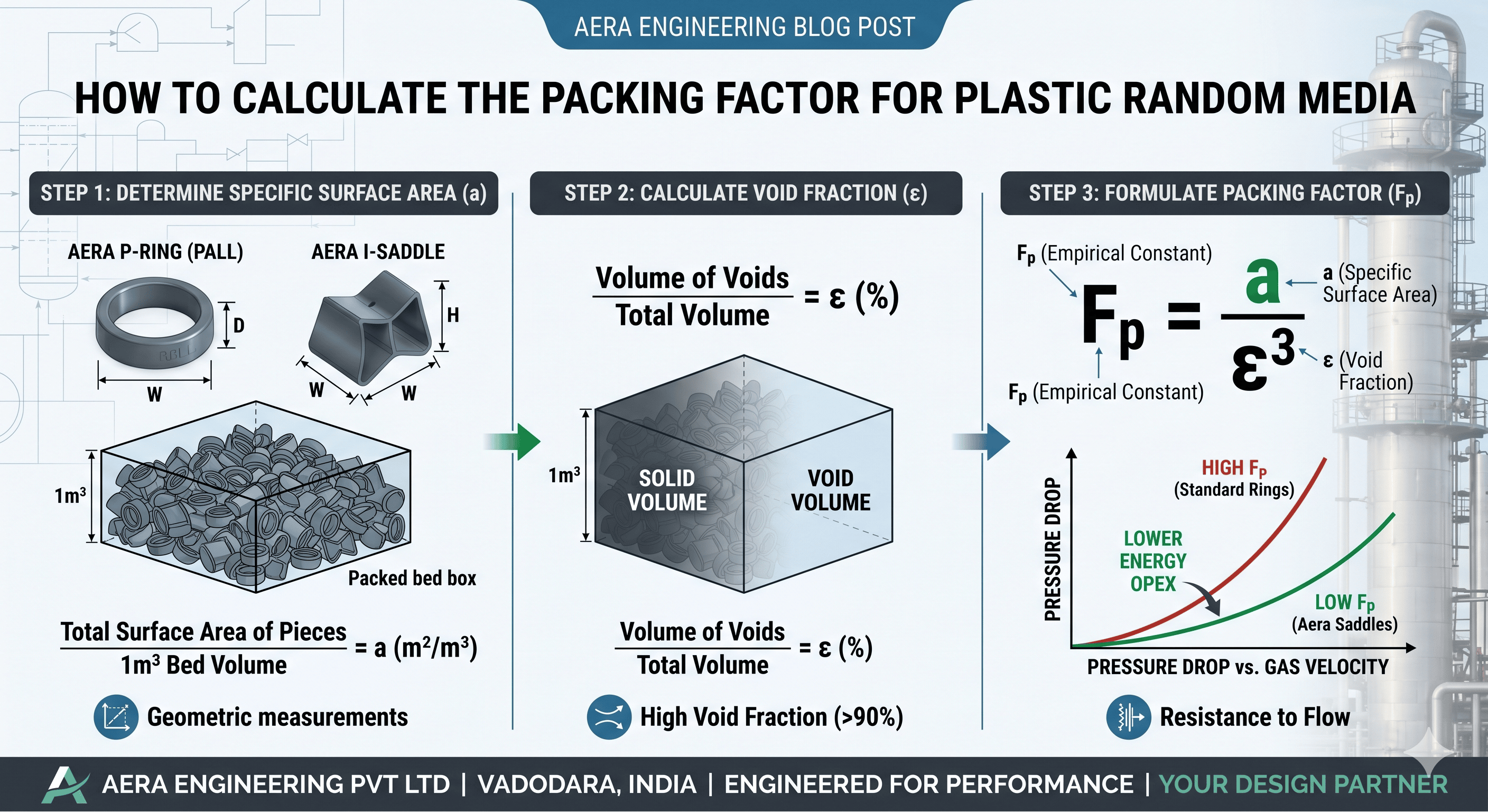
This technical blog is designed to establish Aera Engineering Pvt Ltd as a thought leader in the engineering community. By providing a clear, academic-style guide on a complex calculation, you build trust with process engineers who make the final procurement decisions. In the design of a packed bed tower, one variable stands above all others in determining the efficiency of gas-liquid contact: the Packing Factor. Whether you are designing a new VOC stripper or debottlenecking a refinery column, understanding the packing factor is essential for calculating pressure drop and liquid holdup. At Aera Engineering Pvt Ltd, we provide high-precision Aera P-Rings and I-Saddles with certified packing factors, but understanding the math behind these numbers is vital for every process engineer. What is the Packing Factor ? The packing factor is an empirical constant specific to each type and size of random packing. It represents the ratio of the total surface area of the packing to the cube of the void fraction: F_p = frac{a}{epsilon^3} Where: Specific surface area ($m^2/m^3$) $epsilon$: Void fraction (dimensionless percentage of empty space in the bed) The packing factor is a direct indicator of the resistance to gas flow. A lower $F_p$ generally indicates lower pressure drop and higher capacity. The Step-by-Step Calculation Process While most engineers use the Generalized Pressure Drop Correlation (GPDC) charts, you can calculate or verify the packing factor using the following steps: 1. Determine the Specific Surface Area ($a$) This is the total geometric surface area of the individual packing pieces per unit volume of the tower. For plastic media, this is calculated by multiplying the surface area of a single piece by the number of pieces per cubic meter. 2. Calculate the Void Fraction ($epsilon$) The void fraction is the ratio of the volume of the interstices (empty spaces) to the total volume of the packed bed. $$epsilon = 1 - frac{V_{solid}}{V_{total}}$$ Plastic media like Aera Polypropylene P-Rings typically offer exceptionally high void fractions (often $>90%$), which is why they are preferred for low-pressure applications. 3. Adjust for Wall Effects and Bed Compaction In actual tower operations, the 'Dry Packing Factor' must be adjusted for 'Wet' conditions. As liquid flows down the tower, it coats the packing, effectively reducing the void fraction and increasing the functional $F_p$. Why the Packing Factor Varies Between Media Not all 25mm (1-inch) packings are created equal. The geometry significantly impacts the $F_p$: Raschig Rings: Have a relatively high $F_p$ because their 'closed' walls create more resistance. Pall Rings: The 'windows' in the walls allow gas to flow through the center, significantly lowering the $F_p$. Saddle Rings: Their aerodynamic shape provides the lowest $F_p$ among traditional random media, allowing for maximum throughput. Engineering Impact: Designing for the 'Flood Point' The packing factor is the key input for determining the Flood Point—the velocity at which the gas flow prevents the liquid from descending. High $F_p$: Leads to early flooding and high energy consumption by blower fans. Low $F_p$: Allows for higher gas and liquid loads, making the tower more resilient to process surges. Conclusion: Precision Manufacturing for Predictable Performance At Aera Engineering Pvt Ltd, we utilize precision injection molding to ensure that every batch of packing we export from Vadodara maintains a consistent geometry. This consistency is what allows engineers to rely on our published $F_p$ values for their critical simulations. Need a custom calculation for your tower? Aera Engineering provides technical support for engineers designing complex mass transfer systems. Contact our technical desk for certified $F_p$ data and material compatibility charts. [Download our Technical Design Manual] | Aera Engineering Pvt Ltd | Vadodara, India
2026-04-25T04:31:35

Submit Your Enquiry